A lifep04 battery, more accurately written as LiFePO4, is a rechargeable lithium battery with an iron-phosphate cathode. It is valued for thermal stability, long service life, and dependable output. In practical terms, it can power an electric vehicle, solar storage system, or marine device for many years. Professor John B. Goodenough, a pioneer of lithium-ion cathode materials, said, “The cathode is the key to the rechargeable lithium battery.” His observation helps explain why LiFePO4 chemistry matters so much.
Inside the cell, lithium ions move between the cathode and graphite anode through an electrolyte. During charging, ions travel toward the anode and electrons move through the external circuit. During use, the process reverses. That controlled movement creates usable electrical current. A battery management system monitors voltage, temperature, and cell balance. It helps prevent overcharging and excessive discharge.
The chemistry is not perfect. Nothing is. LiFePO4 cells usually provide lower energy density than nickel-rich lithium batteries. This can mean a heavier battery pack for the same driving range. However, their strong thermal resilience reduces some safety concerns. They also tolerate repeated charge cycles remarkably well. A properly designed pack may deliver thousands of cycles under suitable conditions.
Real performance still depends on temperature, charging habits, wiring, and manufacturing quality. A cold garage can reduce available power. Poor balancing can shorten the pack’s life. Therefore, understanding how a lifep04 battery works requires more than reading its label. It requires examining the complete system, from individual cells to the final application.
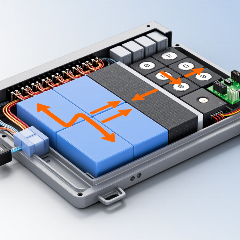
A LiFePO4 battery uses lithium iron phosphate as its cathode material. Its nominal voltage is about 3.2 V per cell, lower than many nickel-based lithium-ion chemistries. During discharge, lithium ions move from the graphite anode through the electrolyte into the LiFePO4 cathode. Electrons travel through the external circuit and power the device. Charging reverses this movement.
The cathode’s olivine crystal structure contains strong phosphate bonds. This structure helps limit oxygen release during overheating and supports stable cycling. In practical testing, however, voltage is not perfectly flat. It changes with temperature, current, state of charge, and aging. A fully charged cell commonly approaches 3.65 V, while the safe operating window depends on the manufacturer’s battery-management settings. The International Energy Agency’s Global EV Outlook 2024 reported that LFP batteries represented nearly half of the global electric-car battery market in 2023. That growth reflects their durability, material availability, and lower cost, although their energy density is generally lower than nickel-rich alternatives.
Tips: Match the charger to the cell voltage. Measure temperatures during high-current use. Do not judge health from voltage alone. Capacity testing is better. A 3.2 V reading does not prove a battery is fully charged; resting time and load conditions matter. Some field measurements look simple, but battery behavior is rarely simple.

In a LiFePO4 cell, lithium ions shuttle between two solid hosts. During charging, ions leave the lithium iron phosphate cathode and travel through the electrolyte. They pass through the separator before entering graphite layers at the anode. Electrons cannot cross that separator. They move through the external circuit instead, storing energy in the graphite. During discharge, the path reverses. Lithium ions return to the cathode, while electrons power a motor, inverter, or small device.
The chemistry usually provides about 3.2 volts per cell, with a relatively flat discharge curve. That steady voltage helps equipment operate predictably. The International Energy Agency reported that LFP chemistry represented about 40% of the global electric-car battery market in 2023. The same report noted that LFP packs cost nearly 30% less than nickel-based alternatives, but offer roughly 20% lower energy density. Numbers matter here.
Inside the cell, ion movement is not perfectly uniform. Temperature, charging speed, and electrode pressure change local current density. A battery-management system watches cell voltage and temperature, then limits charging when conditions become unsafe. Real cells age unevenly. A warm corner may degrade faster than the center. This detail is easy to miss. In practice, careful thermal control and moderate charging rates often matter as much as the chemistry itself. My own reading of technical test reports suggests that simple cycle-count claims deserve caution, because laboratory conditions rarely match daily use.
What Is a LiFePO4 Battery and How Does It Work?
A LiFePO4 battery uses lithium iron phosphate as its cathode material. During discharge, lithium ions move through the electrolyte toward the negative electrode. Electrons travel through the external circuit and power a device. This controlled movement produces stable electrical energy with less heat than many older lithium chemistries.
The key charging limit is 3.65 volts per cell. A proper battery management system should stop charging near this point. Pushing beyond it can increase stress, heat, and capacity loss. A typical cell has a nominal voltage of about 3.2 volts, so a four-cell pack reaches roughly 12.8 volts nominally. That rating makes it suitable for many storage and low-voltage power systems.
Cycle life is often listed between 2,000 and 5,000 cycles. Real results depend on depth of discharge, temperature, charging speed, and storage voltage. A shallow daily cycle may deliver better service than a full discharge each day. Efficiency commonly exceeds 90%, meaning most stored energy returns to the load. Still, wiring, connectors, and conversion equipment create losses. Real-world figures are less tidy. In my experience, careless charging settings can undermine impressive laboratory ratings. Cold weather can also reduce available power, even when the battery appears fully charged. Regular voltage checks and sensible thermal control remain practical safeguards.
A LiFePO4 battery stores and releases energy by moving lithium ions between a phosphate-based cathode and a carbon anode. During charging, ions travel toward the anode. During use, they return through the electrolyte, while electrons flow through the external circuit. This chemistry is valued for stable cycling and strong thermal behavior.
Its safety advantage becomes clearer during overheating. Under severe heating, LiFePO4 may begin decomposing near 270°C, although the exact temperature depends on cell design, charge level, pressure, and test conditions. The phosphate structure holds oxygen more tightly than many layered cathode materials. Less oxygen means less fuel for combustion. As a result, heat release is usually slower, and thermal runaway is harder to sustain.
Still, safer does not mean impossible. A damaged cell, poor wiring, overcharging, or blocked ventilation can create dangerous heat. A battery can feel calm outside while internal damage grows. That is an uncomfortable detail, but it matters. Temperature limits should never be treated as operating targets.
Tips: Use a battery management system with temperature sensing and overcharge protection. Keep cells away from heaters and direct sunlight. Stop using any pack that swells, smells unusual, or becomes hot during light use. Professional inspection is wiser than guessing.
A LiFePO4 battery uses lithium iron phosphate as its cathode material. Each cell produces about 3.2 volts under normal conditions. Four cells connected in series create a 12.8 V battery system. Inside the pack, cells, busbars, insulation, and sensors must work together. Small differences between cells can become important during charging.
The battery management system, or BMS, monitors cell voltage, pack current, and temperature. It can disconnect charging or loads when readings become unsafe. Many BMS units also perform passive balancing by releasing a small amount of energy from higher-voltage cells. Balancing is not magic. A weak cell may still limit the entire pack. In practical testing, loose connections and poor thermal contact often cause more trouble than expected.
Tips: Use a charger designed for LiFePO4 chemistry and follow the cell maker’s voltage limits. Keep the pack dry, secure, and away from direct heat. Avoid charging below the specified low-temperature limit. Check terminals for discoloration or looseness. A fuse near the battery can reduce damage during a short circuit. Do not rely on the BMS as the only safety device. Its protections may be incomplete, incorrectly configured, or misunderstood. I have found that careful wiring inspection catches problems earlier than software readings. Still, every installation deserves review, because real-world conditions rarely match a clean workshop test.
| Category | Parameter | Typical Value or Description | Why It Matters |
|---|---|---|---|
| Cell Chemistry | Cathode material | Lithium iron phosphate, LiFePO4 | Provides a stable olivine crystal structure and strong thermal stability. |
| Nominal cell voltage | Approximately 3.2 V | Used to estimate the voltage of series-connected battery packs. | |
| Maximum charge voltage | About 3.65 V per cell | Charging above the specified limit can accelerate degradation or create a safety hazard. | |
| Recommended operating temperature | Charging: generally above 0 °C; discharging: commonly about −20 °C to 60 °C, subject to cell specifications | Low-temperature charging can cause lithium plating and permanent damage. | |
| Energy storage principle | Lithium ions move between the graphite anode and iron-phosphate cathode during charge and discharge. | Reversible ion movement produces electrical energy without combustion. | |
| Pack Architecture | 12.8 V nominal pack | 4 cells in series, commonly written as 4S: 4 × 3.2 V = 12.8 V | A practical replacement for many 12 V battery systems. |
| 25.6 V nominal pack | 8 cells in series, commonly written as 8S: 8 × 3.2 V = 25.6 V | Suitable for higher-voltage equipment designed for a 24 V-class battery. | |
| Series connection | Increases voltage; amp-hour capacity remains approximately that of one parallel string. | Cells must be matched and monitored so that no individual cell exceeds its limits. | |
| Parallel connection | Increases amp-hour capacity and available current; voltage remains approximately unchanged. | Parallel groups should have similar voltage, capacity, age, and state of charge. | |
| Electrical Performance | Usable energy calculation | Energy in watt-hours ≈ nominal voltage × amp-hour capacity | Example: a 12.8 V, 100 Ah pack stores approximately 1,280 Wh before application losses. |
| Discharge voltage profile | Relatively flat through much of the discharge cycle, followed by a sharper decline near empty. | Voltage alone is less precise than a battery monitor for estimating state of charge. | |
| Charge method | Constant-current/constant-voltage charging using a LiFePO4-compatible charger. | A charger intended only for another lithium chemistry or lead-acid profile may be unsuitable. | |
| Power capability | Determined by cell design, temperature, state of charge, wiring, fuse rating, and BMS current limits. | The battery's amp-hour rating alone does not define safe continuous or peak current. | |
| Round-trip efficiency | Often high compared with many traditional rechargeable battery systems, but varies with current, temperature, and charger settings. | Real-world energy recovery is lower than the theoretical stored energy. | |
| BMS Functions | Cell-voltage monitoring | Measures each series cell or cell group individually. | Pack voltage can appear normal even when one cell is dangerously high or low. |
| Overcharge protection | Disconnects or limits charging when a cell reaches its configured upper threshold. | Prevents individual cells from being driven beyond their safe voltage range. | |
| Over-discharge protection | Disconnects the load when a cell falls below its configured lower threshold. | Helps prevent cell damage caused by excessive discharge. | |
| Overcurrent and short-circuit protection | Uses current sensing and switching devices to interrupt abnormal current. | Protection settings must coordinate with external fuses and the connected load. | |
| Temperature protection | Stops or limits charging and discharging outside permitted temperature ranges. | Temperature limits protect performance, service life, and safety. | |
| State estimation and communication | Some BMS units calculate state of charge, cycle data, alarms, and operating current. | Monitoring improves maintenance and helps identify abnormal conditions early. | |
| Cell Balancing | Passive balancing | Bleeds a small amount of energy from higher-voltage cells through resistors, usually near the top of charge. | Simple and cost-effective, but relatively slow and energy-inefficient. |
| Active balancing | Transfers energy from higher-voltage cells to lower-voltage cells. | Can balance more efficiently, but adds cost, complexity, and control requirements. | |
| Balancing limitation | Balancing cannot repair a weak, damaged, or severely mismatched cell. | A persistent voltage difference requires inspection rather than repeated forced balancing. | |
| Safe Operation | Correct charger | Use a charger with a voltage profile and current limit specified for the LiFePO4 pack. | Confirm the pack's charging instructions before connecting any charger. |
| External protection | Install appropriately rated fuses, disconnects, insulated terminals, and correctly sized conductors. | The BMS is not a substitute for properly designed wiring and overcurrent protection. | |
| Physical installation | Secure the pack against vibration, moisture, crushing, abrasion, and accidental terminal contact. | Mechanical damage and loose connections can cause overheating or failure. | |
| Inspection and storage | Stop using a battery that is swollen, cracked, leaking, unusually hot, or producing an odor; store it in a cool, dry location according to the manufacturer's instructions. | Do not open, puncture, short-circuit, or charge a visibly damaged pack. |
Note: Exact voltage, current, temperature, balancing, and protection thresholds vary by cell design and battery-pack specification. Always follow the pack manufacturer's technical documentation.